CFD Analysis of Heat Exchangers
CFD Analysis of Heat Exchangers
Computational Fluid Dynamics (CFD) has revolutionized the engineering landscape, particularly in the analysis and design of heat exchangers. These critical components are widely used in chemical processing, HVAC systems, and power generation to efficiently transfer heat between two or more fluids. This blog post delves into the importance of CFD analysis in optimizing heat exchanger performance, enhancing design accuracy, and reducing operational costs.
Understanding Heat Exchangers
Heat exchangers are devices designed to transfer heat between two or more fluids at different temperatures. They come in various configurations, including:
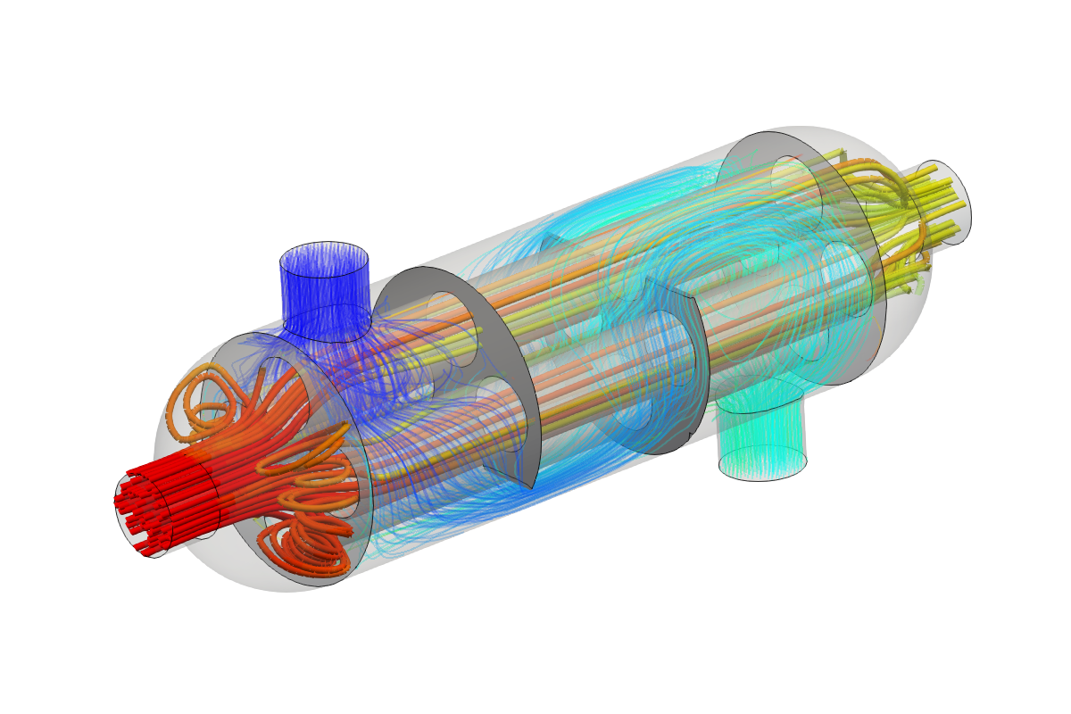
- Shell and Tube Heat Exchangers
- Plate Heat Exchangers
- Air-Cooled Heat Exchangers
- Double-Pipe Heat Exchangers
The selection of a heat exchanger type depends on factors like the fluids involved, temperature ranges, pressure drop constraints, and space limitations. Effective design and operation of these systems can lead to improved energy efficiency and lower operating costs.
The Role of CFD in Heat Exchanger Analysis
CFD provides a powerful tool for simulating fluid flow and heat transfer processes within heat exchangers. The benefits of using CFD in heat exchanger analysis include:
- Enhanced Design Validation: CFD allows engineers to visualize the flow patterns and temperature distribution within the heat exchanger, providing insights that are difficult to obtain through traditional methods.
- Performance Optimization: By simulating various design configurations, engineers can identify optimal geometric features that enhance thermal performance while minimizing pressure drop.
- Cost Reduction: CFD analysis helps to reduce the need for extensive prototyping and testing, which can be time-consuming and expensive.
- Operational Insights: CFD can predict how changes in operating conditions (e.g., flow rates, fluid properties) impact performance, enabling better operational decision-making.
CFD Simulation Process for Heat Exchangers
The CFD simulation process for heat exchangers typically involves several steps:
- Geometry Creation: The first step is to create a detailed 3D model of the heat exchanger, accurately representing all critical components.
- Meshing: The geometry is then divided into smaller elements or cells to create a mesh, which is crucial for solving the governing equations of fluid dynamics.
- Boundary Conditions: Appropriate boundary conditions must be defined, which include specifying inlet velocities, temperatures, and outlet conditions.
- Solver Setup: The CFD solver is configured to simulate the fluid flow and heat transfer phenomena. Selection of the turbulence model (e.g., k-epsilon, k-omega) is critical at this stage.
- Post-Processing: Once simulations are complete, post-processing tools are used to visualize results, such as temperature contours, velocity vectors, and pressure fields.
Challenges in CFD Analysis of Heat Exchangers
While CFD offers numerous advantages, there are challenges to consider:
- Computational Cost: High-fidelity simulations can be computationally intensive, requiring significant computational resources and time.
- Accuracy of Models: The accuracy of CFD results is highly dependent on the choice of turbulence models and numerical methods, necessitating careful selection and validation.
- Complex Geometries: Modeling complex geometries can lead to difficulties in meshing and may require advanced techniques, such as adaptive meshing.
Conclusion
CFD analysis has become an indispensable tool for engineers involved in the design and optimization of heat exchangers. By leveraging advanced simulation techniques, engineers can achieve better performance, enhance energy efficiency, and reduce costs. As computational capabilities continue to improve, the role of CFD in heat exchanger analysis will only grow, paving the way for innovative solutions in heat transfer technology.